*


The Casella counter anemometer erected on a temporary pole after repair. It now turns effortlessly in the slightest breeze.
As obtained, the cups of this superb anemometer were obviously being slowed dramatically by undue internal friction. Never one to ignore a chance to explore a mechanism I started to dismantle the instrument immediately.
Tools: To dismantle the unit you will need some medium sized spanners (wrenches) at least one screwdriver and a pair of bent jaw, circlip pliers.
Workplace: The unit should ideally be placed on a clean, flat wooden bench in good light for dismantling. A shallow container, large enough to store the smaller dismantled parts, should be placed nearby. Preferably where it won't be knocked over and irreplaceable items lost on the floor or the ground! Do not grip the anemometer unit in a bench vice! It is totally unnecessary, likely to damage the precision fits and is very unkind to the original finish! Nor will it allow access to the casing screws under the lid.
The cup rotor shaft is held in place by a circlip hidden inside the top of the bearing housing pipe. This area is hidden beneath the rotor head or hub in normal use. Removing the wind cups from the hub makes the job of dismantling easier but is not essential. Choose your own method depending on your toolbox, skill and patience. Just don't lose or damage anything. Placing an anemometer on a high pole with loose or damaged parts is asking for serious injury for those down below! Take no chances!

Inexpensive circlip pliers. The bent jaw type which you will need to dismantle the anemometer.
My own anemometer unit, as purchased, was stiff to turn. After dismantling it proved to have a corroded counter drive worm and an internally rusty journal bearing. Though it may have been discoloured lubricant which had dried out over time.
Had I persisted in trying to run the anemometer normally it would probably have destroyed itself. Leading to very expensive repairs by the manufacturer. (Where possible or even affordable) Or the unit becoming merely a decorative, but completely static, garden sculpture. Fortunately the obvious stiffness in rotation warned me against leaving the instrument as it was.
The work required to repair these minor internal problems was very simple indeed and took very little time. In fact I spent far more time admiring the beautiful simplicity of the unit and photographing it than actually fixing it. Just don't dismantle the indicator drums!
BTW: Absolutely NO criticism is implied of the seller of my unit in anything written here. I am absolutely delighted and feel very privileged to finally own one of these beautiful and impressively large instruments. I wouldn't be the least surprised if most redundant anemometers don't need similar work when they are bought by weather enthusiasts or collectors. There is no need to be afraid of the unit provided you are armed with the correct tools and quite ordinary "bicycle repairing" skills.

How the rotor hub should look with the cups still attached.
The bronze rotor hub is rather discoloured by exposure to the weather without the protection of the grey paint. This is merely cosmetic. As is the slight damage to other painted areas from knocks and bumps.
Note the doubled (locking) nuts on the cup holding arms and at the top of the rotor hub.

Ideally the cup shaft nuts need a 1/4 BSF ring spanner. A 13mm spanner is rather a tight fit on the arm nuts but will go on if wiggled about.
NB. This is a posed image only to show the method of construction for greater clarity. The parts should be brought closely together and the twin locking nuts fitted and tightened as seen in the image above.
The flat on each cup shaft collar should point upwards to be locked against rotation by the L-shaped locating plate. The cup and hub assembly should rotate anti clockwise when seen from above.
Loosen each top nut and remove it completely before loosening the second nut. The nuts are only locked together by friction. Attempting to undo both nuts at the same time is hard work and may cause permanent damage! If you must use an adjustable spanner then tighten it well to avoid rounding off the nuts. Carefully match hex socket sizes if you have access to a socket set.
Note that the rotor and cup shaft collars are each clearly marked with punched dots. These should be matched on reassembly to ensure a balanced cup rotor unit.
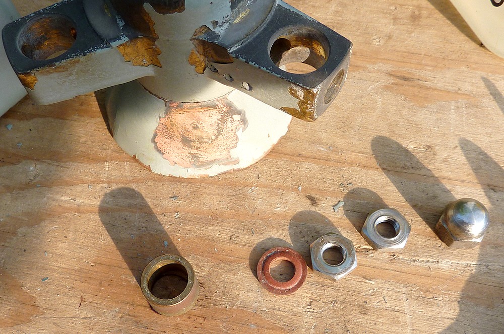 .
.Rotor hub fixings. The bronze bush goes over the main shaft first. Followed by the rotor. Note the crosswire which fits the flat shoulder machined on the shaft. The gasket washer seals the rotor to stop water ingress. Then the two plain lock nuts go on with the decorative domed nut on top. Tighten each nut in turn. No great torque is required. A perfectionist would use two thin spanners to lock the flat nuts together. Cone spanners for bicycle wheel bearing repair might work. See the top image for the fully assembled unit.

The cup shaft retaining plates, nuts and cross drilled screws were all placed in the safety of a shallow container. Loss of any original parts is greatly to be regretted on any vintage or antique instrument. Avoid working over drains, grills, gravel or long grass which might conceal a dropped item. Do NOT use pliers on nuts and screws. It damages them permanently and affords very poor torque to tighten anything afterwards. The same applies to worn out screwdrivers. It is always worth investing in the correct sized spanners and screwdrivers at today's very low prices for good quality tools.

Here the lower casing has been removed exposing the numerical counter unit. The counter is held to the casing lid by two nuts. Even if you should remove the unit do not attempt to dismantle the counter assembly itself.
The lower case can be easily removed by loosening the four screws beneath its rim. Use a well fitting screwdriver to avoid damaging the screws.
The screwed collar and its gasket are unscrewed next. Mine was only finger tight. Avoid using damaging tools if your own sealing ring proves to be rather tight. A pair of pump pliers are probably best. Preferably with some protective wrapping around the collar to avoid surface damage. Once the securing ring is removed the lower casing may then be withdrawn downwards over the bearing housing tube.

One end of the counter and its Tufnol (fibre) drive wormwheel. The corroded worm is just visible, almost hidden below the fibre wormwheel. I am afraid I never thought to photograph the initial corrosion on the worm.
Note the eccentric bush for setting the depth of the counter drum assembly to its countershaft drive.
Note: Different tooth numbers of wormwheel would be necessary for alternative counter readings. The example shown here reads in statute miles. Variations were offered as standard, including metric counter readings.

The newly polished worm. I chose to use the 3-jaw chuck on my lathe to safely spin the main shaft under complete control.
I folded 600 grade emery paper to form a sharp crease. The edge of the crease was then allowed to run repeatedly and automatically along the grooves of the worm as it rotated in the lathe. NO pressure was applied.
Only very fine abrasive paper should be used or the worm's thread form will be permanently damaged. Those without a lathe could roll the shaft on a flat surface while applying the sharp crease of the folded emery paper to the grooves in the worm thread. Patience will be rewarded.
I hesitate to suggest placing the main shaft in the chuck of an electric drill. Somebody is bound to damage the lower bearing surface and then blame me for their own idiocy! Or, possibly worse, try to grip the thread on the top end and have it fly out at high speed!! Use very careful thought before committing yourself to powered assistance.
Note that you need only re-polish the worm if friction is noticed when you try to turn the cup rotor by hand. It should feel completely free to turn without any perceptible friction. Otherwise the anemometer cannot register very light winds.

The stainless steel journal bearing is fixed firmly onto the main shaft. I left it in place and spun the shaft in the lathe. Adding very fine oil and holding the very stiff bearing loosely between my fingertips. This eventually cleared the old and discoloured (rust-stained) lubricant from inside the bearing. I kept wiping the dirty oil away with a tissue until only clean oil was left. The bearing was then wiped repeatedly to ensure no remaining oil would run down the shaft onto the worm. A badly corroded bearing should be replaced. The number is clearly stamped on the outer race.'

Top journal bearing retaining circlip.
This seats in a groove machined in the bearing housing tube. It will be extremely difficult to remove the circlip without a pair of bent jaw, circlip pliers. I tried with straight circlip pliers and it proved impossible to reach the circlip.
Once an expensive luxury, good quality circlip pliers can be obtained very cheaply indeed these days.
Click on any image for an enlargement.
*
Hi I love your blog regarding vintage anemometers and I am trying to obtain a casella cup counter anemometer. I have tried eBay for many years to buy one but was never lucky enough to find one on eBay.. Do you know anyone that has one that they are selling? Or do you have a spare one that you could possibly sell me?
ReplyDeleteRegards
Matthew.
Mathew,
DeleteI am sorry I missed your comment/inquiry. I don't visit all my old blogs regularly.
eBay is still your best bet. Did you know you can save eBay searches using particular search terms? You might try saving "Casella." Another term might be "cup anemometer." Or "vintage anemometer." You maybe notified of uninteresting items but nothing is perfect. I think I remember seeing a Casella or Munro only recently. It was just like mine. Try amn eBay "completed auctions" search.
Regards
Chris