*

 The Casella 1204/1 Mk11 Anemometer is a very high quality wind measuring instrument of similar design to the Munro models. An angled window in the lower casing allows the counter to be read from below. Perhaps with the help of binoculars. Though some models have a "straight ahead" window instead. Suggesting that they were more accessible.
These instruments were used as the meteorological standard around the world for wind measurement. Only later did smaller and lighter anemometers, with remote electric or electronic indication, recording and/or logging, take the place of these older, purely-mechanical instruments.
Relative accuracy to the new generation was eventually lost due to the high cup inertia and friction within the original instruments. Particularly where basic maintenance was non-existent or irregular. This caused the starting (or lowest) recordable wind speed of the device to rise beyond an acceptable level. Which meant that light winds were largely ignored by the instrument. This problem can be easily checked by counting the run-down time when the rotor is spun by hand in still conditions. Complete freedom is obviously desirable. Any noticeable friction (at all) is highly undesirable.
The three large, painted copper cups are carried around on a cast bronze rotor hub fixed to a sturdy, vertical, stainless steel shaft. The shaft is housed in a bearing tube which penetrates the weather-proof casing. The lid of the box casing overlaps the lower box and is sealed with a gasket. The rotor hub has a tapered copper skirt to deflect rain away from the inner bearings.

High quality stainless steel is used for all the exposed fasteners. (nuts, screws and washers) This avoids the inevitable rust and corrosion of what was an expensive instrument to purchase. One which is expected to be continuously exposed to extremes of weather. Out of doors, year round, right across the globe, in all climates.
The casing and rotor hub appear to be made of corrosion resistant bronze. Having a 'brassy' colour where the paint has been damaged by accidental knocks. My own instrument came from a British University department and appears to have been dropped at least once.
The top of the main shaft is supported in a stainless steel, journal-type, ball bearing. The reduced diameter at the bottom of the shaft rotates in what looks like a small bush bearing. It is very difficult to see it well inside the lower tube.
 Inside the case and between the two bearings is a large diameter brass/bronze worm fixed to the main shaft. (A worm is just like a short section of a large diameter, screw thread)
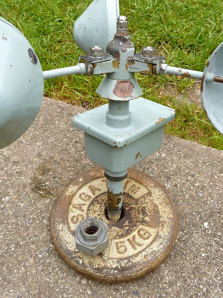
The worm engages with a Tufnol wormwheel through an aperture in the bearing housing pipe. The wormwheel is fixed to a horizontal shaft which drives the digital indicator drums via plastic teeth and a counter shaft also furnished with plastic gears. The indicator drums rotate to numerically record the air which passes the anemometer head in a given time period. The previous (or initial) reading must obviously have been recorded. This is subtracted from the latest number shown on the counter indicator drums. Division by the time interval between counter readings will give the average windspeed over that period.
The galvanised plumbing union is an important part of the anemometer. (Shown resting on the supporting barbell weight I used for the photograph.)
The anemometer screws into the plumbing union and the union screws onto the pole. The threads are all 1/2 " BSP. [British Standard Water Pipe] The union allows the unit to be rotated on its pole and then locked firmly into place by tightening the union itself. This safely avoids applying unnecessary torque to the supporting pipe. Or to the anemometer itself, simply to make the window face a particular way for easier reading. Iron water pipe and fittings are usually available in most places. Allowing inexpensive poles, masts and brackets to be put together, on site, to match local needs. Take care to tighten the union properly! My own installation started to wobble after a week or two. Requiring more ladder work.
The standard height for anemometer installation is 10 meters on open ground. That's over 30 feet high and will require a pole with guy lines or a lattice mast. Any tall, local obstructions will lower the effective height of the anemometer. Such details are vital for accurately recording meteorological data for scientific purposes. The amateur can make do with less height. Provided they don't post their wind records online without a clear description of their instrument's situation appended. There is still the risk of causing distortion of the local weather records.
Many owners of inexpensive commercial "weather stations" will often connect automatically to the internet with the software provided. Often having fixed their anemometer below the eaves of their bungalow! Probably in a sheltered, suburban garden surrounded in other buildings, shrubs and trees! It is not snobbery to suggest that any wind readings from such a situation will be completely useless for any serious purposes.
The numeral indicator drums are very similar to the old fashioned bicycle mileometers but built much larger. (And hopefully far more reliably than their smaller cousins) The larger digits allow them to be read more easily from the ground. Possibly using a telescope or binoculars to avoid a hazardous climb in all weathers. A written record of the steadily advancing digits would be kept in a logbook or diary by the meteorologist. Or any other person responsible for keeping wind and weather records.
A short video of my Casella anemometer in action:
The illusion of movement is entirely due to camera shake despite my using my 3/8 " water pipe steady-cam. The anemometer is not used as a measuring device so the tree in the background is unimportant. The birch tree is about 8-10 feet beyond the anemometer.
Though the pole only reaches 4 ' above the roof the instrument is much steadier on a 3/4 " BSP pipe than on the smaller 1/2 ". Note I have fitted a reducing adapter and lock nut in place of the original plumbing union. I was unable to reach the union safely from a ladder with any tool large enough to tighten the union effectively. It worked loose over a very short time so I removed it out of safety concerns. Galvanized pipe and fittings are all very inexpensive.
Remember to put safety first when climbing ladders (or masts) and fixing any items (or tools) which might fall on innocent victims far below.
If you are uncomfortable on ladders then hire a professional to do the job rather than take any unnecessary risks. An aerial rigger has such experience and the necessary skill set to do a proper job of erecting an anemometer for you. Make sure you give clear instructions to face the counter window in the correct direction. I would suggest pointing the counter South to avoid staring into the sun to take your readings! Particularly if you are going to need optical assistance (a tripod mounted telescope or binoculars) to read the counter on a tall mast or pole. An inexpensive bird watching telescope with an angled eyepiece would be ideal because the telescope probably needs to be tipped upwards. The telescope could be even be set up by a window indoors to allow reading the counter in comfort.
A counterbalanced pole hinged on a bar between very strong posts would allow the instrument to be lowered at will but would lose wind data while lowered. It would need to be carefully balanced to avoid irreparable damage to your priceless anemometer! A 30 ' (10m) pole with a heavy anemometer on top is a very long lever indeed! It would need to be brought down and re-erected with great care over a clear stretch of ground to be done safely.
Here's just one design of tilting flag pole:
http://www.poletech.com/TiltingPoles.aspx
It might need to be made stronger with a heavier counterweight to support a heavy anemometer: You'd need to talk to the manufacturers about your specific application. Given the enormous drag on a large flag in a good wind an anemometer might be well within its capacity given enough counterweighting.
A bottom-heavy balance would allow the tilting pole (and anemometer) to be pulled down with a rope. The rope would be attached to the top of the pole and could hang neatly down the pole and be tied off when not in use. A secure locking mechanism between the pole and its supporting posts would be required to keep the pole vertical even when heavy counterweights are used. The supporting posts or poles would need to be set in concrete. The supporting/hinge bar could be done at lower cost using large, galvanized pipe fittings. The pole connection would need to be suitable strong. Probably requiring a tapered or stepped size pipe construction.
Click on any image for an enlargement.
*
Do you have any data for this anemometer? I have a similar one where the mechanical counter has been replaced with a worm drive and contact, presumably to drive a remote counter. Regards, Tony Erwood. Shetland.
ReplyDeleteHi Tony
ReplyDeleteUnfortunately I didn't get any paperwork with my MkII. I was planning to add a bicycle computer magnet and contact to the rain shield area to read windspeed directly. The only way I could calibrate it would be to compare it with my two handheld anemometers. I have searched for data online using every imaginable search term without success. Given the huge number of MkIIs used as meteorological references there must be something on them in the public domain somewhere. Casella did not respond to my email.
Regards
Chris