Saturday 17 August 2013

Casella M106/61 'Sensitive' anemometer

This is a smaller counter anemometer by Casella.

Examination of the instrument would suggest that it is splash proof but has no long-term, weather resistant properties. It is thus unlikely to be intended for permanent set-up out of doors for meteorological purposes.

Its remarkable sensitivity might suggest a mine ventilation measuring device but even this seems unlikely. The instrument was obtained from an ex-govt source which specialising in ex-military hardware. Yet the case is not painted green nor covered in typical heavy military symbols or codes.


It came in a neat, plywood, protective case.

The lid contains a graph for defining average wind speed against rotor revolutions.

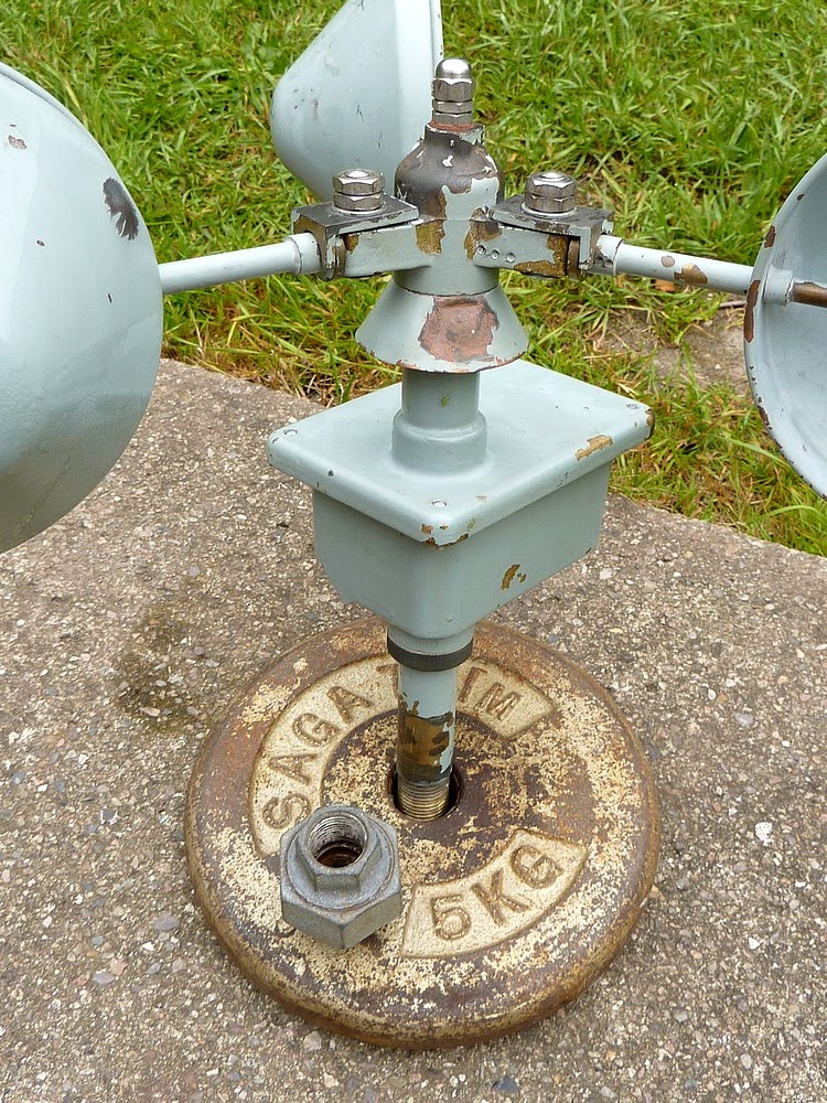
The rough piece of 18mm plywood is only a temporary base to allow the instrument to stand up safely for photography.


The base casting would normally fit in the empty spring clip on the left inside the case.

Note the neat clamps and compact arrangement of the instrument within the case. There is no obvious sign in or on the case to which this base casting might have been affixed.


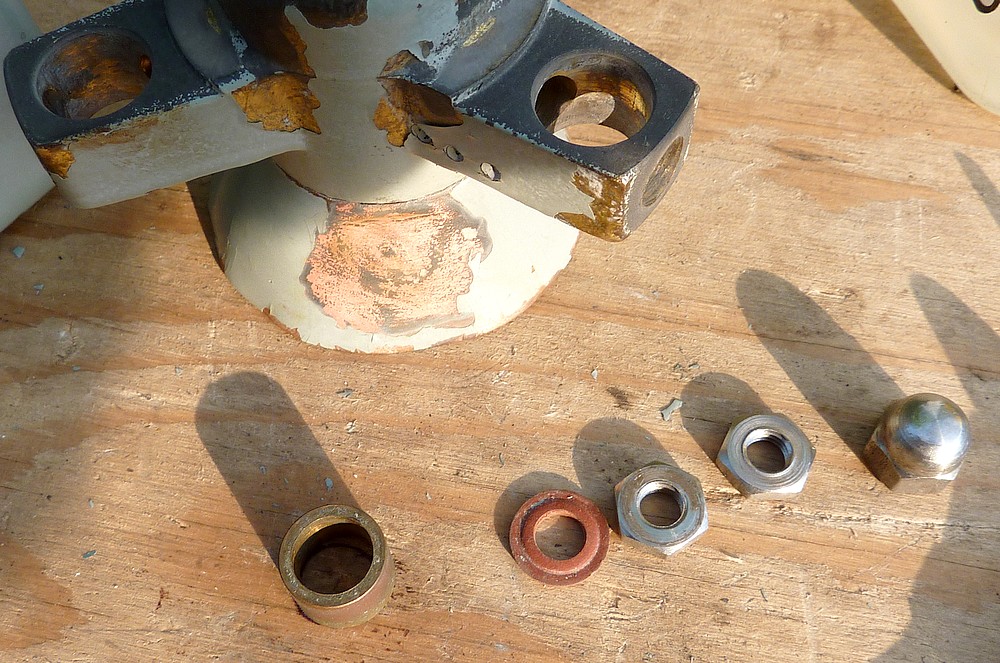
Here the instrument has been removed from the case to show the taper to the bottom of bearing shaft. This fits in a matching taper in the base casting.


The number on the rear of the dial and the source suggests that the instrument was used to measure wind speed for military gunnery control.


 The carrying handle and manufacturer's label.


The instrument set up on the temporary plywood base.

The overcast weather conditions make for shadowless photography but the exposure is too long to capture the rotating cups sharply. The cups rotate freely in only a breath of air movement. Often too light to sense with bare forearms.


The Casella counter dial reads directly to 100 revolutions. Sub dials read in 100s and 1000s of revolutions. Useful for longer duration measurements.


The shaft-gripping collet inside the rotor head is clearly seen here.


 Here is the point on top of the stainless steel shaft where the rotor sits.


Here is a scan of the original Casella graph sheet. I have added the axes text to the image for clarity. The original axes labels were handwritten.


An older video of the Casella anemometer in action:


Further to my rather wild guesses above I found another Casella for sale with rather more original information. The Casella 'Sensitive' Anemometer was intended  for recording low wind speeds or air movement. It could be used to check industrial and mine ventilation.  It was also used in aeronautics. The Counter/Air Velocity graph above only rises to 30 fps which is about 9 m/s, 30kph or 20mph. Hardly suitable for normal weather measurement. Thanks to its jewelled, low friction main shaft bearings and low inertia it started at very low air velocities compared to the much larger and heavier Casella/Munro MkII meteorological type of anemometer.


Click on any image for an enlargement.


Sunday 14 July 2013

Casella MkII Anemometer Clean and Repair Pt.2.


Newly polished worm visible through the bearing housing aperture. This section is always hidden inside the casing for weather protection. The protected area of paint will offer a better match to the original finish if it is decided to repaint a scruffy unit.

Top journal bearing seated down inside the shaft housing and the circlip safely in place. After removal of the circlip the shaft can be simply withdrawn upwards out of the bearing housing tube. The worm will follow on the lower end of the shaft. 

The circlip must be seated properly or the complete cup rotor could lift in a gale! It doesn't need a rocket scientist to work out the damage to life and property if that should happen on a tall mast!  So don't lose that circlip or attempt a non-standard replacement. A steel circlip is very likely to rust away even if you were lucky enough to  find one of the exact, same size. 


Close-up view of the drum drive gearing and eccentric bearing bush for the countershaft. (Holding the small white gears)

Loosening the protruding screw will allow fine adjustment of the depths (overlaps) of the gear teeth between the layshaft and counter drums.

The numeral drums need some gentle cleaning. A soft toothbrush and some diluted washing up liquid suggests itself here.


The discolouration of the numerals makes them more difficult to read in normal use. Because they require the high contrast of white on black to be well seen in poor light or at a distance.


Lower housing retaining ring and its paper gasket.

A small drainage hole is provided at the lowest point of the box casing. This is to allow condensation to escape. Make sure the hole is clear. Condensation is unavoidable where metal is heated and cooled in a moist atmosphere. The mass of metal lags behind the more rapidly rising and falling air temperature. Often resulting in heavy condensation. Just being exposed to the cold night sky can cause radiant heat loss and heavy dewing. 

One cup arm was quite bent as purchased. Presumably from the fall which had badly dented the rain skirt and did rather less damage to one of the cups.

I used the ends of the grooved plywood jaws of a B&D workbench to grip the shaft without damage. The wide flat jaws of an adjustable spanner allowed precise and delicate leverage during the cup shaft straightening process. Being brass, the shafts must never be hammered! Hammering hardens brass (and bronze) making it more brittle. Even the shock of the initial bend might have hardened the cup shaft. So I was extremely careful as I "sneaked" gently towards perfect straightness.

Heating the brass shaft to redness, to soften it, would have burnt the remaining paint and spoiled the original finish too much. I used a range of tools to hammer the dent out of the copper rain skirt. The original paint had already been lost in that area. Probably too much flexure to maintain paint adhesion. Though cosmetically a little "untidy" I will not be in any hurry to make the instrument look like new again. Raised high on a post in my private, rural garden nobody is ever going to see it up close except me.

I used a tiny drop of sewing machine/bicycle oil on each counter bush and at the bottom end of the shaft before rebuilding the unit. Once reassembled the anemometer rotor now turned without any noticeable friction at all. I should have cleaned the drum numerals too but was eager to see the instrument in action. As soon as I placed it up on the pole it turned in a gentle breeze which I could hardly feel on my bare arms. A remarkable improvement over the original condition. Previously the rotor would not move even if I blew hard into each cup. Now it is hardly ever still.

Update 1: My original 1/2" BSP galvanised water pipe proved to be too thin and flexible in stronger winds. So I moved up to 3/4" BSP. This pipe size is much stiffer and the anemometer no longer rocks in the wind. I swapped the 1/2" union for a 3/4" to 1/2" reducer. I had to clean the rough end of the 1/2" thread in the lathe to allow the anemometer to screw into the reducer. The reducer makes for a neater appearance and the whole unit can be faced as desired by slackening a large, galvanised, lock nut.

Update 2: I took down my MKII anemometer due to a severe storm warning from the DMI. I took the opportunity to clean the counter window, drums and digits. The fiber wormwheel proved to be nicely polished now having run for some time with the cleaned and polished worm. Local maximum wind speeds (gusts) published by the DMI exceeded 41m/s or 90mph! Not a pleasant experience having suffered damage to our home in the Great Storm of 1999. Fortunately there was no damage this time except for some broken branches in the trees on our garden border. At least six trees were felled  by the wind within a mile of our home.

Unlike the Great Storm, there seemed to be very little obvious structural damage, this time. Apart from the usual damage to domestic greenhouses and plastic roofed carports. Many of these seem very poorly equipped to cope with high winds.


Click on any image for an enlargement.
*

Saturday 13 July 2013

Casella MkII Anemometer Clean and Repair Pt.1.

*
The Casella counter anemometer erected on a temporary pole after repair. It now turns effortlessly in the slightest breeze.

As obtained, the cups of this superb anemometer were obviously being slowed dramatically by undue internal friction. Never one to ignore a chance to explore a mechanism I started to dismantle the instrument immediately.

Tools: To dismantle the unit you will need some medium sized spanners (wrenches) at least one screwdriver and a pair of bent jaw, circlip pliers.

Workplace: The unit should ideally be placed on a clean, flat wooden bench in good light for dismantling. A shallow container, large enough to store the smaller dismantled parts, should be placed nearby. Preferably where it won't be knocked over and irreplaceable items lost on the floor or the ground! Do not grip the anemometer unit in a bench vice! It is totally unnecessary, likely to damage the precision fits and is very unkind to the original finish! Nor will it allow access to the casing screws under the lid.

The cup rotor shaft is held in place by a circlip hidden inside the top of the bearing housing pipe. This area is hidden beneath the rotor head or hub in normal use. Removing the wind cups from the hub makes the job of dismantling easier but is not essential. Choose your own method depending on your toolbox, skill and patience. Just don't lose or damage anything. Placing an anemometer on a high pole with loose or damaged parts is asking for serious injury for those down below! Take no chances!


Inexpensive circlip pliers. The bent jaw type which you will need to dismantle the anemometer.

My own anemometer unit, as purchased, was stiff to turn. After dismantling it proved to have a corroded counter drive worm and an internally rusty journal bearing. Though it may have been discoloured lubricant which had dried out over time.

Had I persisted in trying to run the anemometer normally it would probably have destroyed itself. Leading to very expensive repairs by the manufacturer. (Where possible or even affordable) Or the unit becoming merely a decorative, but completely static, garden sculpture. Fortunately the obvious stiffness in rotation warned me against leaving the instrument as it was.

The work required to repair these minor internal problems was very simple indeed and took very little time. In fact I spent far more time admiring the beautiful simplicity of the unit and photographing it than actually fixing it. Just don't dismantle the indicator drums!

BTW: Absolutely NO criticism is implied of the seller of my unit in anything written here. I am absolutely delighted and feel very privileged to finally own one of these beautiful and impressively large instruments. I wouldn't be the least surprised if most redundant anemometers don't need similar work when they are bought by weather enthusiasts or collectors. There is no need to be afraid of the unit provided you are armed with the correct tools and quite ordinary "bicycle repairing" skills.


How the rotor hub should look with the cups still attached.

The bronze rotor hub is rather discoloured by exposure to the weather without the protection of the grey paint. This is merely cosmetic. As is the slight damage to other painted areas from knocks and bumps.

Note the doubled (locking) nuts on the cup holding arms and at the top of the rotor hub.


Ideally the cup shaft nuts need a 1/4 BSF ring spanner. A 13mm spanner is rather a tight fit on the arm nuts but will go on if wiggled about. 

NB. This is a posed image only to show the method of construction for greater clarity. The parts should be brought closely together and the twin locking nuts fitted and tightened as seen in the image above.

The flat on each cup shaft collar should point upwards to be locked against rotation by the L-shaped locating plate. The cup and hub assembly should rotate anti clockwise when seen from above.


Loosen each top nut and remove it completely before loosening the second nut. The nuts are only locked together by friction. Attempting to undo both nuts at the same time is hard work and may cause permanent damage! If you must use an adjustable spanner then tighten it well to avoid rounding off the nuts. Carefully match hex socket sizes if you have access to a socket set. 

Note that the rotor and cup shaft collars are each clearly marked with punched dots. These should be matched on reassembly to ensure a balanced cup rotor unit. 

.
Rotor hub fixings. The bronze bush goes over the main shaft first. Followed by the rotor. Note the crosswire which fits the flat shoulder machined on the shaft. The gasket washer seals the rotor to stop water ingress. Then the two plain lock nuts go on with the decorative domed nut on top. Tighten each nut in turn. No great torque is required. A perfectionist would use two thin spanners to lock the flat nuts together. Cone spanners for bicycle wheel bearing repair might work. See the top image for the fully assembled unit.


Cast bronze rotor hub after removal to show the internal cross-wire. This seats on the flat machined on the shaft.  Presumably the wire would shear if the system were subject to serious shock or internal system seizure. A hard (machined) shoulder in the rotor hub might well cause more damage to the counter mechanism in the event of a serious fault. Possibly leading to arm failure to the cups and falling debris. As a deliberately designed weak point the cross-wire acts rather like a mechanical fuse against possible accidents.

The cup shaft retaining plates, nuts and cross drilled screws were all placed in the safety of a shallow container. Loss of any original parts is greatly to be regretted on any vintage or antique instrument. Avoid working over drains, grills, gravel or long grass which might conceal a dropped item. Do NOT use pliers on nuts and screws. It damages them permanently and affords very poor torque to tighten anything afterwards. The same applies to worn out screwdrivers. It is always worth investing in the correct sized spanners and screwdrivers at today's very low prices for good quality tools.


Here the lower casing has been removed exposing the numerical counter unit. The counter is held to the casing lid by two nuts. Even if you should remove the unit do not attempt to dismantle the counter assembly itself.


The lower case can be easily removed by loosening the four screws beneath its rim. Use a well fitting screwdriver to avoid damaging the screws.


The screwed collar and its gasket are unscrewed next. Mine was only finger tight. Avoid using damaging tools if your own sealing ring proves to be rather tight. A pair of pump pliers are probably best. Preferably with some protective wrapping around the collar to avoid surface damage. Once the securing ring is removed the lower casing may then be withdrawn downwards over the bearing housing tube.


One end of the counter and its Tufnol (fibre) drive wormwheel. The corroded worm is just visible, almost hidden below the fibre wormwheel. I am afraid I never thought to photograph the initial corrosion on the worm. 

Note the eccentric bush for setting the depth of the counter drum assembly to its countershaft  drive.   

Note: Different tooth numbers of wormwheel would be necessary for alternative counter readings. The example shown here reads in statute miles. Variations were offered as standard, including metric counter readings. 


 The newly polished worm. I chose to use the 3-jaw chuck on my lathe to safely spin the main shaft under complete control. 

I folded 600 grade emery paper to form a sharp crease. The edge of the crease was then allowed  to run repeatedly and automatically along the grooves of the worm as it rotated in the lathe. NO pressure was applied.  

Only very fine abrasive paper should be used or the worm's thread form will be permanently damaged. Those without a lathe could roll the shaft on a flat surface while applying the sharp crease of the folded emery paper to the grooves in the worm thread. Patience will be rewarded.

I hesitate to suggest placing the main shaft in the chuck of an electric drill. Somebody is bound to damage the lower bearing surface and then blame me for their own idiocy! Or, possibly worse, try to grip the thread on the top end and have it fly out at high speed!!  Use very careful thought before committing yourself to powered assistance. 

Note that you need only re-polish the worm if friction is noticed when you try to turn the cup rotor by hand. It should feel completely free to turn without any perceptible friction. Otherwise the anemometer cannot register very light winds.  

Wormwheel, showing some wear caused by the the corroded worm. Hopefully the nicely polished worm will self-repair the teeth of the wormwheel over time. Eventually leading to a polished appearance. I have emailed Casella requesting advice on wormwheel:worm lubrication but have yet to hear back from them. It seems unlikely that any is required in such a lightly loaded application. Some lubricants can actually attack bronze and brass. So an expert choice is needed here. The worm corrosion seemed unlikely unless a non-approved substance had been applied. Or the device's casing had been left open and exposed to a damp or corrosive atmosphere. 

The stainless steel journal bearing is fixed firmly onto the main shaft. I left it in place and spun the shaft in the lathe. Adding very fine oil and holding the very stiff bearing loosely between my fingertips. This eventually cleared the old and discoloured (rust-stained) lubricant from inside the bearing. I kept wiping the dirty oil away with a tissue until only clean oil was left. The bearing was then wiped repeatedly to ensure no remaining oil would run down the shaft onto the worm. A badly corroded bearing should be replaced. The number is clearly stamped on the outer race.'


Top journal bearing retaining circlip.

This seats in a groove machined in the bearing housing tube. It will be extremely difficult to remove the circlip without a pair of bent jaw, circlip pliers. I tried with straight circlip pliers and it proved impossible to reach the circlip.

Once an expensive luxury, good quality circlip pliers can be obtained very cheaply indeed these days. 


Click on any image for an enlargement.
*

Thursday 11 July 2013

Casella Mk11 counter anemometer: W1204/1

*


The Casella 1204/1 Mk11 Anemometer is a very high quality wind measuring instrument of similar design to the Munro models. An angled window in the lower casing allows the counter to be read from below. Perhaps with the help of binoculars. Though some models have a "straight ahead" window instead. Suggesting that they were more accessible.

These instruments were used as the meteorological standard around the world for wind measurement. Only later did smaller and lighter anemometers, with remote electric or electronic indication, recording and/or logging, take the place of these older, purely-mechanical instruments.

Relative accuracy to the new generation  was eventually lost due to the high cup inertia and friction within the original instruments. Particularly where basic maintenance was non-existent or irregular. This caused the starting (or lowest) recordable wind speed of the device to rise beyond an acceptable level. Which meant that light winds were largely ignored by the instrument. This problem can be easily checked by counting the run-down time when the rotor is spun by hand in still conditions. Complete freedom is obviously desirable. Any noticeable friction (at all) is highly undesirable.  

The three large, painted copper cups are carried around on a cast bronze rotor hub fixed to a sturdy, vertical, stainless steel shaft. The shaft is housed in a bearing tube which penetrates the weather-proof casing. The lid of the box casing overlaps the lower box and is sealed with a gasket. The rotor hub has a tapered copper skirt to deflect rain away from the inner bearings.


High quality stainless steel is used for all the exposed fasteners. (nuts, screws and washers) This avoids the inevitable rust and corrosion of what was an expensive instrument to purchase. One which is expected to be continuously exposed to extremes of weather. Out of doors, year round, right across the globe, in all climates.

The casing and rotor hub appear to be made of corrosion resistant bronze. Having a 'brassy' colour where the paint has been damaged by accidental knocks. My own instrument came from a British University department and appears to have been dropped at least once.

The top of the main shaft is supported in a stainless steel, journal-type, ball bearing. The reduced diameter at the bottom of the shaft rotates in what looks like a small bush bearing. It is very difficult to see it well inside the lower tube.

Inside the case and between the two bearings is a large diameter brass/bronze worm fixed to the main shaft. (A worm is just like a short section of a large diameter, screw thread)


The worm engages with a Tufnol wormwheel through an aperture in the bearing housing pipe. The wormwheel is fixed to a horizontal shaft which drives the digital indicator drums via plastic teeth and a counter shaft also furnished with plastic gears. The indicator drums rotate to numerically record the air which passes the anemometer head in a given time period. The previous (or initial) reading must obviously have been recorded. This is subtracted from the latest number shown on the counter indicator drums. Division by the time interval between counter readings will give the average windspeed over that period.

The galvanised plumbing union is an important part of the anemometer. (Shown resting on the supporting barbell weight I used for the photograph.)  

The anemometer screws into the plumbing union and the union screws onto the pole. The threads are all 1/2 " BSP. [British Standard Water Pipe] The union allows the unit to be rotated on its pole and then locked firmly into place by tightening the union itself. This safely avoids applying unnecessary torque to the supporting pipe. Or to the anemometer itself, simply to make the window face a particular way for easier reading. Iron water pipe and fittings are usually available in most places. Allowing inexpensive poles, masts and brackets to be put together, on site, to match local needs. Take care to tighten the union properly! My own installation started to wobble after a week or two. Requiring more ladder work.

The standard height for anemometer installation is 10 meters on open ground. That's over 30 feet high and will require a pole with guy lines or a lattice mast. Any tall, local obstructions will lower the effective height of the anemometer. Such details are vital for accurately recording meteorological data for scientific purposes. The amateur can make do with less height. Provided they don't post their wind records online without a clear description of their instrument's situation appended. There is still the risk of causing distortion of the local weather records. 

Many owners of inexpensive commercial "weather stations" will often connect automatically to the internet with the software provided. Often having fixed their anemometer below the eaves of their bungalow! Probably in a sheltered, suburban garden surrounded in other buildings, shrubs and trees! It is not snobbery to suggest that any wind readings from such a situation will be completely useless for any serious purposes. 

The numeral indicator drums are very similar to the old fashioned bicycle mileometers but built much larger. (And hopefully far more reliably than their smaller cousins) The larger digits allow them to be read more easily from the ground. Possibly using a telescope or binoculars to avoid a hazardous climb in all weathers. A written record of the steadily advancing digits would be kept in a logbook or diary by the meteorologist. Or any other person responsible for keeping wind and weather records. 

A short video of my Casella anemometer in action:


The illusion of movement is entirely due to camera shake despite my using my 3/8 " water pipe steady-cam. The anemometer is not used as a measuring device so the tree in the background is unimportant. The birch tree is about 8-10 feet beyond the anemometer. 

Though the pole only reaches 4 ' above the roof the instrument is much steadier on a 3/4 " BSP pipe than on the smaller 1/2 ". Note I have fitted a reducing adapter and lock nut in place of the original plumbing union. I was unable to reach the union safely from a ladder with any tool large enough to tighten the union effectively. It worked loose over a very short time so I removed it out of safety concerns. Galvanized pipe and fittings are all very inexpensive.

Remember to put safety first when climbing ladders (or masts) and fixing any items (or tools) which might fall on innocent victims far below.

If you are uncomfortable on ladders then hire a professional to do the job rather than take any unnecessary risks. An aerial rigger has such experience and the necessary skill set to do a proper job of erecting an anemometer for you. Make sure you give clear instructions to face the counter window in the correct direction. I would suggest pointing the counter South to avoid staring into the sun to take your readings! Particularly if you are going to need optical assistance (a tripod mounted telescope or binoculars) to read the counter on a tall mast or pole. An inexpensive bird watching telescope with an angled eyepiece would be ideal because the telescope probably needs to be tipped upwards. The telescope could be even be set up by a window indoors to allow reading the counter in comfort.

A counterbalanced pole hinged on a bar between very strong posts would allow the instrument to be lowered at will but would lose wind data while lowered. It would need to be carefully balanced to avoid irreparable damage to your priceless anemometer! A 30 ' (10m) pole with a heavy anemometer on top  is a very long lever indeed! It would need to be brought down and re-erected with great care over a clear stretch of ground to be done safely.

Here's just one design of tilting flag pole:

http://www.poletech.com/TiltingPoles.aspx

It might need to be made stronger with a heavier counterweight to support a heavy anemometer: You'd need to talk to the manufacturers about your specific application. Given the enormous drag on a large flag in a good wind an anemometer might be well within its capacity given enough counterweighting.

A bottom-heavy balance would allow the tilting pole (and anemometer) to be pulled down with a rope. The rope would be attached to the top of the pole and could hang neatly down the pole and be tied off when not in use. A secure locking mechanism between the pole and its supporting posts would be required to keep the pole vertical even when heavy counterweights are used. The supporting posts or poles would need to be set in concrete. The supporting/hinge bar could be done at lower cost using large, galvanized pipe fittings. The pole connection would need to be suitable strong. Probably requiring a tapered or stepped size pipe construction.


Click on any image for an enlargement.
*