Tuesday, 10 January 2017

Cassella MkII anemometer re-lube to stop noise.

 *

UPDATE: After several years of problem free use the anemometer has started squeaking and whistling loudly. The sound is obviously being amplified by the roof to which it is attached.  I put the noise down to a lack of lubrication of the worm/wormwheel. I discussed polishing the worm in the text above. 

It seems the brass/Tufnol interface cannot survive long term without some lubrication.  Though I found no trace present when purchased secondhand. I emailed Casella about lubrication but received no reply. Presumably these instruments are now obsolete and no staff remain who have any knowledge of their maintenance. I shall try oiling the wormwheel to see if that helps. Re-polishing the brass/bronze worm may also be necessary. I'm waiting for a still day before I start trying to lower the supporting pipe.  

A further update: Having taken down the anemometer and removed the lower plate the fiber wormwheel was dark but lightly polished. The brass/bronze[?] worm looked rather dull. I applied some Castrol LMP grease to the worm and re-erected the anemometer on its pipe. Only for it to start groaning and whistling again! Obviously not due to a lack of lubrication on the worm. So, back down it came and I removed the cup rotor to apply a few light oil drops to the top and bottom ball bearing races. When it went up again it remained completely silent and spun far more freely. It is now reacting to light gusts far more quickly and slowing more slowly.

Click on any image for an enlargement.
*

Wednesday, 29 April 2015

Ventus W831 First impressions: Part 2

(  )
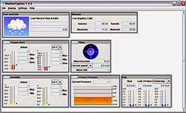
The worst problems, so far, lie with the provided software. Weather Capture Advance Version 1.4 is supplied on a DVD.  The display unit must be connected to a computer with the supplied 2meter long USB cable for the software to function. Otherwise it gives a warning to connect and promptly deletes itself from the screen! While the supplied software is running it constantly updates its monitoring of remote unit transmission on a bar scale counting down from 2 minutes. Note that though an "expand to full screen" button is shown above the display box it remains determinedly fixed at about 1/2 of my total screen width. [See image of screen grab.]

Some screen settings produce on-screen boxes with very obviously chopped off  sides and bottom. And, even more importantly, no visible buttons to choose, update or close that setting below the adjustable choices! I could only hit Enter on my computer keyboard to remove several settings boxes from my computer screen! The instructions book shows the settings boxes being much wider and deeper than actually appear on my computer screen. Which is very irritating to say the least and completely unforgivable at this price point! The software might be corrupted or is simply well below the perceived standard of the Ventus W831 Weather Station itself. Very disappointing! I shall uninstall and reload the software to check for any improvement. [It didn't!]

Much more information on the bundled software in the previous post.

I have placed the external thermo-hygro wireless sensor under the deep northern eaves of the house. The unit is hanging right beside the external sensor of my Indoor/Outdoor, cabled, digital thermometer. Both sensors avoid any sun warming effects and are well clear of the underside of the already shady side of the roof. Nevertheless, temperatures shown on the Ventus are sometimes 2-3 degrees higher than with my digital thermometer in bright afternoon sunshine. Which is slightly worrying. Unless I am getting a reading from a thermometer in the wind measuring instrument which I remember was mentioned in the instructions. I shall have to look into this. [See paragraph below.]

The wind measuring unit is out in full sunshine and will be subject to solar heating effects on the casing. Which are almost guaranteed to read higher than a shaded sensor. If this text disappears I will have tracked down the problem. The Hygro-thermo unit is marked 5 channel and an LED flashes [about] every 35 seconds. Presumably this is the period between wireless updates. A small LCD screen shows Channel number temperature and humidity. For some reason changing the batteries for freshly bought new ones immediately stopped the display screen from registering outside temperature on the display module! Having left the display unit on battery power all night it relocated the external sensor. It then exactly matched the In/Out digital thermometer which I have previously relied on for temperature readings. Both outdoor readings of the separate devices now agree to within 1/10 of a degree F in overcast conditions! Though experience shows that they do vary relative to each other.
                                                                                                                
I have yet to get any rainfall readings so cannot comment on the efficiency of the tilting-bucket, measuring device. We have a lot of falling vegetation from the many trees in my back garden. So I may put the rainfall measuring unit on the south side of the house facing a field sized lawn with mown grass.

Levelling is important to the unit's tipping bucket function and a round bubble level is hidden inside the bottom of the case. The unit is quite attractive and unlikely to spoil the appearance of its location if bright white plastic is acceptable. There may be security issues with some locations and an open topped, box will easily disguise the contents. Though not one of metal or it may block the wireless signal back to the display head indoors. The lightweight unit must be fixed down to a flat, easily draining surface to avoid being blown away in a gale!

A rough screen fits loosely inside the funnel mouth to stop larger debris falling in and blocking the mechanism. How it will cope with the countless wind-borne Birch seeds and such fine debris is as yet unknown. The instructions suggest cleaning the remote wireless units at weekly intervals. Which means the unit must be easily accessible without undoing the four fixing screws on the base.

The image below shows the rainfall unit dismantled by turning the two black knobs and lifting the funnel unit free. The central tipping bucket device, bubble level and bottom drain holes are all visible. The funnel moulding has a battery compartment which is sealed with a gasket and cover plate with seven tiny screws. Note that the funnel can only be re-inserted the correct way round. This is indicated by the different lengths of the funnel base matching the heights of the supporting brackets inside the case. Which means that it must be possible to see inside the empty casing when cleaning the unit. Something to think about when choosing a site and fixing platform. Or one could choose to [say] have the battery plate facing the user [or away] when inserting the funnel into the case.
 
The claimed range of the remote wireless sensor units is 100m in a straight line. Walls, metal and other structures in a building may well affect this range. Presumably the rainfall measuring device works by counting the number of tips of the see-saw bucket device electronically. Rainwater fills one side of the tipping bucket  to unbalance the rocker. So that it eventually tips and empties automatically in readiness for another refill by more falling rain. The area of the funnel opening relative to the tipping bucket size provides the rainfall depth in whichever units the user chooses on the display and computer software. It is important that the device is fixed out in the open so that it is not sheltered by trees, bushes or building overhangs. Otherwise it is likely to read very low local rainfall!

I just noticed that the weather forecasting display on the top left of the screen [cloud, sunshine, etc] changed on cue from sunny periods to cloudy as cloud covered the sky.A nice confirmation that it is working as intended. As I write this the screen is showing the sun peeking from behind the clouds. Exactly on cue as the cloud thins and the sky brightens. The forecast weather display relies entirely on barometric pressure. At other times the screen has remained fixed on showing cloudy in a perfectly clear sky from dawn to late at night!

Overall, I would say that the W831 is of good quality but the supplied software needs some work. There are some serious doubts developing about indicated wind speed. The cup rotor has been spinning well on occasions but the display has yet to rise above 3 m/s. [About 6.5 mph!]  With no rain forecast I haven't set up the wireless rainfall sensor yet. I know it works because the bucket tipped when I was examining the unit and the display updated rainfall by 1.4mm. So I am happy with my birthday present for the moment. Thank you, Dear!  :ø)

An update: The wind today, Wed. 29th April, is gusting and highly variable as to direction. It is forecast to gust to 15m/s locally. [Over 30mph] I have been regularly monitoring wind speed but the Ventus display unit has never risen above 3.4, then 3.8 and now 4.1 m/s at 14.00. [~7.5, 8.5 and 9mph respectively using the 2.2 conversion factor.]

Earlier I tried holding a cheap, hand-held digital anemometer at about half mast height and briefly registered 6 m/s.[13 mph]  Though this device uses a small propeller with a very much faster response to gusts than the larger Ventus rotor. The much larger, vintage Casella has been rotating briskly but certainly not remotely as fast as it has sometimes in the past. The wind gusts are expected to peak at 15 m/s at around 15.00pm this afternoon. There is a clear run of air to the Ventus anemometer from the South-west. Because of its greater lag during gusts the Ventus is expected to display a lower average speed on the display unit. Only a prolonged gust would raise the reading significantly.

NOTE: I have discovered that the Ventus display unit can be set to Gust by pressing suitable buttons. The updating still only occurs at about 30 second intervals but at least it registers wind speed more as I prefer it. The normal [default] settings average the measured wind speed over 5 minutes. Which helps to explain the very low readings until now. 

I have still not heard from Ventus about the software problems or possible alternatives.

Click on any image for an enlargement.

(  )

Sunday, 19 April 2015

Weather Capture Advance 1.4

)

The Weather Capture Advance 1.4 software comes on a disk with the Ventus W831 Weather Station. Multiple languages are offered.

While it provides a wide range of measurements in an attractive and easily readable form there are some problems with the settings options.

The first problem is that full screen viewing is not available despite the usual "Maximise" button being provided.

Here is a larger image of only the [software] viewing screen area captured on a sunny morning in mid April with very light winds and no rain.

Note the very large range of readings available. The screen can be saved as an Excel file or as a text file. Both can be recorded automatically or at many different intervals chosen by the user.

I particularly like the wind rose to indicate wind direction and speed. A handy feature for recording highly complex data. Making it larger would have been desirable but there isn't much room on such a complex graphic.  


The Location settings box is clearly chopped off at the bottom. There is no means to fine tune location despite all the adjustable scales being provided unless one chooses USR [defined] which does not allow any location name to be entered. Otherwise, moving the cursor over them produces no reaction. What is missing at the bottom?


Here the Temperature/Humidity settings adjustment box is chopped off at the right. How can one make any meaningful choices regarding dewpoint? 


These are the display settings for the software chart/screen. [Not the W831 display unit] All is well here with quite a decent range of options.


These are the W831 display screen settings.

Note how the settings box is chopped off on the right. There is no settings confirmation button so one can only press 'Enter' on the computer keyboard to confirm changes. Rain and Wind cannot be altered.

BTW: I have adjusted all the box sizes in PhotoFiltre image handling software. In reality each Settings adjustment box has its own size.

I tried uninstalling and reloading the software without any noticeable change.


To add to the confusion this is how the software appears on Ventus' own product website:

As can be seen it is completely unlike anything on the supplied disk.

I have contacted Ventus by email to see if this software is available.


Click on any image for an enlargement.
*

Friday, 17 April 2015

Ventus W831 Weather Station. First impressions.


The lack of direct reading of wind speed and direction prompted the arrival of a Ventus W831 weather station as a present for my birthday.

The overall impression is one of high quality plastic casting and the complexity of available readings on the display unit.

The 28½ pages of English language instructions are competently written but sometimes rather complex to take in on first reading. They also lack some important details. Perhaps more importantly, they are sometimes, simply incorrect. For example, they talk about releasing latches for hatches on battery compartments. When in reality all the batteries are hidden behind moulded plastic plates with sealing rubber gaskets. All of which require quite a small screwdriver to remove and replace several tiny screws in each case. I found a jewellers screwdriver with a straight blade worked best on the cross-head screws.

Only the indoor display unit has easily accessible batteries. Working on the remote units out of doors would introduce a very high risk off loss of these tiny screws. It is strongly suggested that the batteries are changed with the units brought down and resting on a lipped tray to catch any escaping screws! This may seriously affect where the units can be sited to allow easy removal.

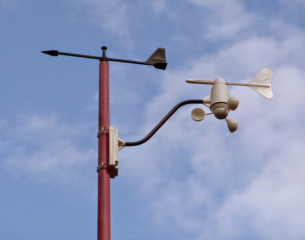
As can be seen in these images I have added the combined, all-plastic anemometer and wind vane unit to my wind surfing mast. Simple stainless steel bar clamps and 2"/50mm long screws are provided and allowed easy fixing of the wind instrument base to my mast. Though the screws were only just long enough for my use, most owners would probably use a smaller diameter pipe.

The all white, Ventus wind vane is rather easier to see against the background trees than my original black yachting arrow. Though seen against a bright sky it can appear quite dark in silhouette.

I originally bought this lightweight, fibreglass mast very cheaply from a flea market to support a simple plastic wind vane borrowed from a yachting application. The GRP mast is very light but stiff and provides perfect support for lightweight instruments such as these. Though it does flex slightly in strong winds it has the advantage of raising the wind reading units some 5 metres off the ground without the risk of it causing damage or injury. Which might well occur if a heavier metal or wooden mast fell in a storm.

Ideally the mast ought to be 10 metres high to comply with meteorological standards. Even higher for situations with obstructions like trees and buildings. Only an open field would really allow the minimum height of 10m for truly accurate wind measurements. I decided that 5 meters was ample for my situation but then I am not expecting professional standards. Adding an aluminium extension pole to the mast only added more flexibility to the mast itself.

At least my wind measuring instruments are erected in the open and not slung under the eaves of a bungalow or carport surrounded in dense shrubbery. Which is quite a common sight in many cases as I cycle the lanes of Denmark. Weather stations are remarkably popular decorations for Danish homes. Though very few owners seem to grasp the need for height and clear exposure to obtain accurate wind readings. No doubt some of these devices are also connected to the Internet. They feed this glaringly incorrect information out to a wider audience as if it contributed to the sum of all knowledge. The Ventus W831 does not offer such a live Internet connection. Only an application which allows weather data to be saved on one's home computer.

I mounted the Ventus wind apparatus just below the original wind vane to ensure there was no physical interference. The extension arm was arranged to point south to provide the "cleanest" air from the prevailing wind directions. SW and SE are the norm for my location. Though, interestingly, the wind was coming from the north on the day I set everything up. Thankfully both vanes are following each other very closely. So I can be sure there are no interference problems despite the very unusual wind direction meeting the mast first after filtering through tall but open trees. The Ventus is much more sensitive to changes in direction of light winds thanks to small, stainless steel, journal, ball bearings. So shaft friction is at a [very low] minimum.

In this image I have dimensioned the case and rather small screen of the display unit. The screen is actually slightly smaller than my Imperial dimensions suggest. A difficult photographic subject whether the screen is lit or not. The protective plastic screen cover is rather shiny and readily reflects well lit backgrounds. I have adjusted the image brightness to better match the actual view. The screen is actually quite dark but legible in both cases of lit and unlit. The displayed text, graphs and symbols appear slightly sharper than these images suggest. Since the screen relies on reflection in the unlit mode it helps to have it placed in a good light but not directly reflecting a window. Reading it by artificial light will probably require that the screen is lit after dusk.

The buttons along the bottom of the screen make an irritating electronic squeal from inside the display case when released. Nor do they always have the desired effect! Particular problems exist around the wind speed settings and labels. The Set button steps through changes which should really be changed by the arrow keys. Wind chill is fixed in the Centigrade scale as far as I can discover. Which hardly makes sense when Fahrenheit temperature scales are chosen for display.

Here the screen is lit with the compact [plug in] 7.5V power supply. The display unit takes four internal AA batteries but they would drain if the screen was lit constantly. There are useful options for control of screen illumination but the PS is essential for a constantly lit screen. 

Lacking batteries and switching off the power supply caused the screen to return to default settings on start-up next day! I had to reset the display to m/s wind speed and Fahrenheit temperature scales. The location had also changed from Copenhagen to Berlin.

Once a city is entered I can't see how any finer location setting is possible. The adjustable scales are shown on the bundled software screen but they are greyed out. Rather strangely, there is no option to allow fine adjustment of location. No batteries are supplied with the Ventus W8311. An omission which caught us out as no fewer than eight  'AA' size batteries are required. Four in the display unit and two each in the wind, hygro-thermo and rainfall units respectively. Harvesting used batteries from various clocks and thermometers around the house provided enough for the wind and hygro-thermo units to be tested. The display head and rainfall would have to wait until I had reached the shops.

Low wind speed reading is really remarkably sensitive. With readings down to 1/10th of one meter/second! Far more sensitive than my large, all brass, copper and bronze vintage Casella anemometer. However, there is quite a lag between movement of the Ventus rotor and screen updates appearing indoors. The same goes for the wind vane. With very long pauses between changes to angles of pointing after I have watched the vane turn. I placed the mast outside so that I could easily watch the wind mast over the top of my computer monitor while sitting in front of a window. I shall have to time the separation between updates to confirm exactly how long they are. [About 35 seconds assuming a change in pointing or wind speed]

See W831 First impressions Pt 2 for more.

Click on any image for an enlargement.
*

Wednesday, 14 January 2015

Casella combined cup anemometer and wind vane

*

This most attractive, cased wind measuring instrument was auctioned in 2014 on eBay(UK).

However, the seller was not open to bids from outside the UK. It sold on a single bid.

I have borrowed the excellent auction images for non-profit, educational use.

Parts of the wind vane show slight weathering which has produced a delightful, natural patina. Leading one to suppose that the unpainted finish is totally original. There is no sign of the typical, overall, grey paint used for permanently mounted meteorological instruments having been removed. In fact there is slight corrosion typical of copper around the anemometer cups. This is only likely to be cosmetic and can be easily cleaned off if desired. In the absence of professional clock cleaning fluids, ammonia, soft soap and water will do.


Note how well every item has its own location and protection against movement within the quality [mahogany?] carrying case. Such a travel case provides ready clues to the replacement and checking that all parts have been safely rehoused following dismantling after use in the field. The loss of a single item would probably make the device useless in the absence of spares. Though I note a rather large object is missing in the front, right corner space. Mounting blocks are fitted there but the space is vacant. The space available looks identical to that of the flange space alongside.

The instrument is provided with hooked, steel, ground pegs, guy lines with tension toggles and a flange-mounted stub mast. This suggests that the instrument was designed to be portable and for temporary erection only. Perhaps for use by expeditions. One can but guess as to the base upon which the mounting flange would rest in use. A handy tree stump, pipe or a sturdy tripod perhaps?


The bare, copper cups of the anemometer must have been most attractive turning brightly in the sunshine. The bronze casing of the head looks deliberately well finished. Despite the overall bare metal finish, the entire construction follows normal practice for British met-office approved instruments. Usually provided by established companies like Casella and Munro. This particular instrument is from Casella and the anemometer parts look [almost] identical to my own Mk2.

The anemometer is of the mechanical counter type and measures in miles. An observer would note the number visible in the counter window. Then read the number again after a fixed period of time. Subtracting the first number from second would allow the measurement of the wind at that location. The counter window being arranged horizontally suggests that the instrument was not usually raised very far above the observer. Mast mounted instruments would probably have a downward facing window for easier reading. Though a horizontal window might well have been used where easy access was possible via fixed ladders.

The wind vane is also entirely mechanical, weight counterbalanced and rotates below the anemometer. Its pointing angle being read off the large, clear, supplied protractor. Which is graduated by battens in 10 degree steps. Longer battens at 30 degree steps and digits to indicate the 90 degree angles. Most common wind vanes use the compass points.


Click on any image for an enlargement.
*

A vintage Wilh.Lambrecht pitot tube airflow test meter.

*
I was lucky to find a very high quality measuring instrument in a wooden case at very low cost. It uses the pitot tube principle to measure airflow at the tip of the 'hockey stick' measuring wand.

It might have been used for measuring airflow in pipes or ventilation ducts.

The cylindrical meter reads in m/s. [Meters per second] The black handle can house two 'C' size batteries. These would light the small torch bulb which shines though a glass window in the meter base.Which would illuminate the measuring scale in poor conditions or even at night.
The bent main tube [wand?] is slightly damaged cosmetically. While the lower part of the wand is protected with a plastic coating. It is possible the damage was caused during normal use by an industrial ventilation engineer. The rest of the instrument is in fine condition as if from careful use.


Here is the active tip. The slot must be an air balancing vent. The orange cap has a hole in the centre of the nose to accept the airflow to be tested.

Something long and thin is missing from the slot provided in the case. Perhaps an alternative tube to fit inside the instrument? Or even a cleaning device?

The small vial has a label but has no contents. This vial is usually stored in a hole bored in one of the support bulkheads near the instrument's handle.


Here is the paper label found in the small glass vial.
My limited understanding of German suggests:
"Replacement nozzle 0,5 "
[A comma is used to define the decimal place on the Continent.]


Here is a close-up of the meter and one of its internal scales.

The main tube [wand] can be removed by unscrewing the central knurled ring.

The two large, knurled knobs on top the meter head rotate the four internal meter scales into view. The small, indicator is seen at rest in the meter window at the '0' position.

The scales are mounted on a rotatable white drum and are graduated as follows: 0-2.6 m/s. 0-8 m/s. 0-18 m/s. 0-50 m/s.

Which means that the device can measure over a range from roughly 0 - 110 mph. Since there are no visible moving parts one must assume that calibration between the ranges is made automatically by changes made internally.


Here is the connection between the test 'wand' and the top of the meter head. Note the perforations in each component and the very high quality of manufacture. Most of the visible components and fixing screws seem to be made of stainless steel or finely machined aluminium alloy.


Here is the small light bulb for illuminating the internal scales.

The base of the "torch" handle is provided with a standard tripod screw, mounting hole in a sturdy, knurled, screw in bush.


And here is the opal window through which the bulb shines.


Here I am testing the instrument in the open air on a windy day. A small electronic 'fan' anemometer is fixed near the head of the pitot tube for comparison. Both devices seem to agree but with varying reaction times to gusts.


This device cannot be easily used for measuring wind speed because it does not point continuously into the wind. Nor does it seem particularly suited to outdoor use.


Lambrecht meteo still manufacture a whole range of environmental measurement instruments at Göttingen, Germany.

http://www.lambrecht.net/de/home


Click on any image for an enlargement.
*


Thursday, 2 January 2014

Adding a bike computer to a Mk2 anemometer.

*
It would be fun to be able to directly read the windspeed from my Casella MkII anemometer. Using bicycle computers to obtain a speed reading from its rotating magnet and sensor system is nothing new. The copper rain skirt fitted to the anemometer's cup rotor provides a perfect magnet site. Requiring only a very small hole to hold the spoke magnet safely tucked under the skirt. The spoke clamp, usually attached to the magnet, can be discarded. The wired sensor works as normal and is fixed with zip ties to the rotor shaft housing just below the rotor skirt. I added a simple clamp from a bicycle front gear changer to ensure the sensor was securely fixed. Any movement over time might cause direct contact between magnet and sensor. This would lock up the rotor and might even cause damage. Not least to the bike computer components.

The magnet sensor is completely waterproof by design. So only needs its cable to be brought down the pole to the computer head bracket. (Also referred to as the shoe or docking station) Small contacts in the shoe match those on the back of the computer head or display unit. 

A large watch battery is usually housed inside the display head to provide the readings. Six months of service is possible when the bicycle is ridden every day. Bike computer's are usually self-starting when the sensor notices a fresh magnet impulse after going into rest or sleep mode. However, the wind is far more constant than a bicycle is usually ridden so the battery may drain more quickly. 

Other than speed a bicycle computer can offer average readings. Though one should be careful to avoid reading fallacies due to low or zero wind speed over given measurement periods. The average will be based on the total time even if no readings were taken during the measuring period. 

There are several problems associated with adding a bicycle computer to an existing anemometer. The active circumference of the cup rotor is an unknown. Even if we measure the radius to the centre of each cup from the centre of the rotor shaft this may not help. It will requiring repeated resetting of circumference to obtain an accurate wind speed reading while comparing readings with another anemometer. Bicycle computers use the circumference of the wheel to be able to register speed and distance while counting pulses from the magnet's passage past the sensor. (Wheel or rotor rpm (counted from the pulses) x circumference will give the speed over time)  Unfortunately there is slippage of the cups in the wind. It is not a direct drive. 

Using another anemometer to calibrate the Casella will require care. Can one trust the reference anemometer? Are they both working at the same height and in the same wind conditions? Are they affecting each other? Is the reference anemometer able to accept wind from all points of the compass like a 3 cup anemometer can?  Many digital anemometers have a small propeller or fan in an aperture in the housing. Care is required to ensure the wind is "on axis" with the rotating fan blades.

Climbing a tall ladder to read a bicycle computer is just silly. You want the computer screen to be easily read at ground level. Or even elsewhere. Unfortunately, wireless bicycle computers have a very short range between sensor and head. Were it otherwise the problem of placing the display head in a more accessible place would be almost trivial. Apart from the higher cost of a wireless computer compared with a wired model, of course.  

Cutting into and extending the fine wires between the head contact shoe and sensor is possible with care. Though this in itself introduces at least two further problems.Will there be a voltage drop along the greatly extended cable? Will the soldered joints be waterproof? If the extension cable has resistance then there might not be enough voltage from the watch battery in the head to ensure successful operation of the head. Will the extended cable act as a lightning conductor? 


How will the voltage be increased if necessary? The head has no room for an extra battery and the batteries have a fixed voltage in each size. Wires could be soldered to the battery contacts inside the head and then brought out through the back sealing cover. Another form of battery could then be connected to ensure extended periods of service. While also providing a higher voltage if it proves essential to operate the bicycle computer despite the much longer cable.  Though I doubt any sensible cable would add any resistance. Ordinary, double insulated, lighting flex would probably do.

An update: I have fitted the magnet and tried different circumference settings on the bike computer. A setting of 4000 and miles produced great sensitivity and about a 10mph reading by pushing the cups quickly by hand. At least this offers a ballpark figure to start experimenting. As the head is easily unclipped from its shoe the circumference settings are easily changed. Though it a a fairly slow process because the computer has to be reset completely from scratch each time.

I measured about 30 yards/metres of double insulated, 0.7m^2, twin lighting flex in series (for 60 metres total) at about 0.4 Ohms. So absolutely no need to worry about voltage drop.

Here are the wheel magnet and bike wheel computer sensor. The sensor is fixed to a bicycle, front gear changer, seat tube clamp with zip ties for security. 

Well, now I have the system set up with a new bike wheel sensor. This had better wiring which allowed me to solder the ends direct to the twin core lighting flex. The other end I soldered the flex direct to the the computer head contact shoe. On a windy day like today with gusts to 15m/s I have hit 30 mph readings several times using the mph and 4000 circumference computer settings.

Comparisons with my handheld anemometers showed similar maximum readings but the Mk2 was incredibly slow to speed up and slow again during gusts. It had tremendous "inertia" compared with the tiny propellers on the handheld electronic devices.

I have screwed the shoe to the shed at head height below the anemometer so I can read it easily. I was going to run the flex to the house but was short by a few yards.

Trying to build my modest collection of vintage, British, cup anemometers is proving very difficult. Sellers using eBay(UK) are automatically blocking all overseas bids. Which means they sell for absolute peanuts. Fine if you live in the UK. Foolish for the seller if the potential buyers live elsewhere. 

*

Saturday, 17 August 2013

Casella M106/61 'Sensitive' anemometer

This is a smaller counter anemometer by Casella.

Examination of the instrument would suggest that it is splash proof but has no long-term, weather resistant properties. It is thus unlikely to be intended for permanent set-up out of doors for meteorological purposes.

Its remarkable sensitivity might suggest a mine ventilation measuring device but even this seems unlikely. The instrument was obtained from an ex-govt source which specialising in ex-military hardware. Yet the case is not painted green nor covered in typical heavy military symbols or codes.


It came in a neat, plywood, protective case.

The lid contains a graph for defining average wind speed against rotor revolutions.

The rough piece of 18mm plywood is only a temporary base to allow the instrument to stand up safely for photography.


The base casting would normally fit in the empty spring clip on the left inside the case.

Note the neat clamps and compact arrangement of the instrument within the case. There is no obvious sign in or on the case to which this base casting might have been affixed.


Here the instrument has been removed from the case to show the taper to the bottom of bearing shaft. This fits in a matching taper in the base casting.


The number on the rear of the dial and the source suggests that the instrument was used to measure wind speed for military gunnery control.


 The carrying handle and manufacturer's label.


The instrument set up on the temporary plywood base.

The overcast weather conditions make for shadowless photography but the exposure is too long to capture the rotating cups sharply. The cups rotate freely in only a breath of air movement. Often too light to sense with bare forearms.


The Casella counter dial reads directly to 100 revolutions. Sub dials read in 100s and 1000s of revolutions. Useful for longer duration measurements.


The shaft-gripping collet inside the rotor head is clearly seen here.


 Here is the point on top of the stainless steel shaft where the rotor sits.


Here is a scan of the original Casella graph sheet. I have added the axes text to the image for clarity. The original axes labels were handwritten.


An older video of the Casella anemometer in action:


Further to my rather wild guesses above I found another Casella for sale with rather more original information. The Casella 'Sensitive' Anemometer was intended  for recording low wind speeds or air movement. It could be used to check industrial and mine ventilation.  It was also used in aeronautics. The Counter/Air Velocity graph above only rises to 30 fps which is about 9 m/s, 30kph or 20mph. Hardly suitable for normal weather measurement. Thanks to its jewelled, low friction main shaft bearings and low inertia it started at very low air velocities compared to the much larger and heavier Casella/Munro MkII meteorological type of anemometer.


Click on any image for an enlargement.


Sunday, 14 July 2013

Casella MkII Anemometer Clean and Repair Pt.2.


Newly polished worm visible through the bearing housing aperture. This section is always hidden inside the casing for weather protection. The protected area of paint will offer a better match to the original finish if it is decided to repaint a scruffy unit.

Top journal bearing seated down inside the shaft housing and the circlip safely in place. After removal of the circlip the shaft can be simply withdrawn upwards out of the bearing housing tube. The worm will follow on the lower end of the shaft. 

The circlip must be seated properly or the complete cup rotor could lift in a gale! It doesn't need a rocket scientist to work out the damage to life and property if that should happen on a tall mast!  So don't lose that circlip or attempt a non-standard replacement. A steel circlip is very likely to rust away even if you were lucky enough to  find one of the exact, same size. 


Close-up view of the drum drive gearing and eccentric bearing bush for the countershaft. (Holding the small white gears)

Loosening the protruding screw will allow fine adjustment of the depths (overlaps) of the gear teeth between the layshaft and counter drums.

The numeral drums need some gentle cleaning. A soft toothbrush and some diluted washing up liquid suggests itself here.


The discolouration of the numerals makes them more difficult to read in normal use. Because they require the high contrast of white on black to be well seen in poor light or at a distance.


Lower housing retaining ring and its paper gasket.

A small drainage hole is provided at the lowest point of the box casing. This is to allow condensation to escape. Make sure the hole is clear. Condensation is unavoidable where metal is heated and cooled in a moist atmosphere. The mass of metal lags behind the more rapidly rising and falling air temperature. Often resulting in heavy condensation. Just being exposed to the cold night sky can cause radiant heat loss and heavy dewing. 

One cup arm was quite bent as purchased. Presumably from the fall which had badly dented the rain skirt and did rather less damage to one of the cups.

I used the ends of the grooved plywood jaws of a B&D workbench to grip the shaft without damage. The wide flat jaws of an adjustable spanner allowed precise and delicate leverage during the cup shaft straightening process. Being brass, the shafts must never be hammered! Hammering hardens brass (and bronze) making it more brittle. Even the shock of the initial bend might have hardened the cup shaft. So I was extremely careful as I "sneaked" gently towards perfect straightness.

Heating the brass shaft to redness, to soften it, would have burnt the remaining paint and spoiled the original finish too much. I used a range of tools to hammer the dent out of the copper rain skirt. The original paint had already been lost in that area. Probably too much flexure to maintain paint adhesion. Though cosmetically a little "untidy" I will not be in any hurry to make the instrument look like new again. Raised high on a post in my private, rural garden nobody is ever going to see it up close except me.

I used a tiny drop of sewing machine/bicycle oil on each counter bush and at the bottom end of the shaft before rebuilding the unit. Once reassembled the anemometer rotor now turned without any noticeable friction at all. I should have cleaned the drum numerals too but was eager to see the instrument in action. As soon as I placed it up on the pole it turned in a gentle breeze which I could hardly feel on my bare arms. A remarkable improvement over the original condition. Previously the rotor would not move even if I blew hard into each cup. Now it is hardly ever still.

Update 1: My original 1/2" BSP galvanised water pipe proved to be too thin and flexible in stronger winds. So I moved up to 3/4" BSP. This pipe size is much stiffer and the anemometer no longer rocks in the wind. I swapped the 1/2" union for a 3/4" to 1/2" reducer. I had to clean the rough end of the 1/2" thread in the lathe to allow the anemometer to screw into the reducer. The reducer makes for a neater appearance and the whole unit can be faced as desired by slackening a large, galvanised, lock nut.

Update 2: I took down my MKII anemometer due to a severe storm warning from the DMI. I took the opportunity to clean the counter window, drums and digits. The fiber wormwheel proved to be nicely polished now having run for some time with the cleaned and polished worm. Local maximum wind speeds (gusts) published by the DMI exceeded 41m/s or 90mph! Not a pleasant experience having suffered damage to our home in the Great Storm of 1999. Fortunately there was no damage this time except for some broken branches in the trees on our garden border. At least six trees were felled  by the wind within a mile of our home.

Unlike the Great Storm, there seemed to be very little obvious structural damage, this time. Apart from the usual damage to domestic greenhouses and plastic roofed carports. Many of these seem very poorly equipped to cope with high winds.


Click on any image for an enlargement.
*